
Grid connected testing of photovoltaic inverters
Photovoltaic inverters convert the direct current voltage generated by solar panels into alternating current energy and connect it in parallel to the power grid. To ensure the quality of power supply and test the impact of photovoltaic inverters connected to the grid, various specifications and testing standards have been developed.

Composition of testing system
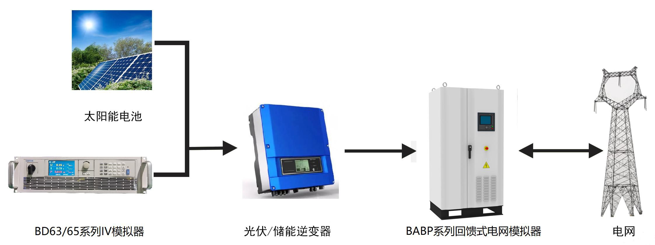
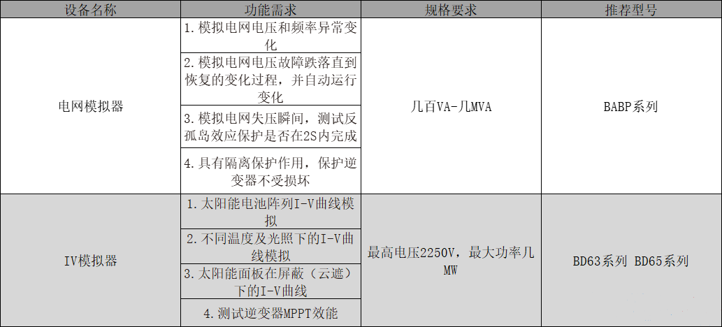
According to the standard requirements and testing items, build the testing platform as shown in the following figure:
Low (zero) voltage ride through grid connection test
Low Voltage Ride Through (LVRT) is an important grid connected test in standard testing projects. According to the low-voltage ride through regulation, when the grid voltage drops for a period of time, grid connected devices such as solar inverters or wind power generation still need to maintain output until the grid power returns to normal.
The BABP series power grid simulator can simulate and output various low-pass waveforms through simple settings, making it convenient for users to test.
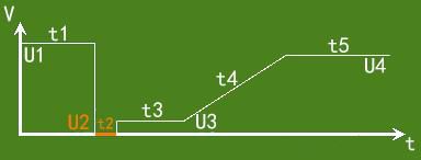
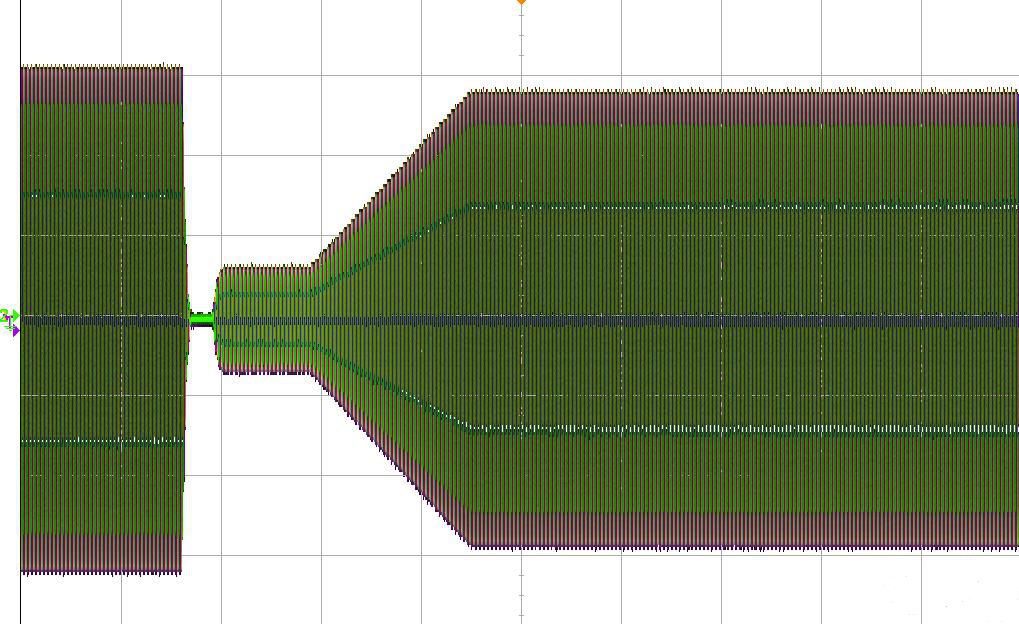
Users can set parameters such as U1-U4 and t1-t5 according to the interface prompts. The power supply will automatically generate a low (zero) voltage ride through curve and directly output it to the inverter terminal, which is simple and efficient. The following figure shows the actual waveform captured by the oscilloscope:
Simulation of power grid distortion
Simulating power grid distortion, abnormal fluctuations, and three-phase imbalance is also an important item in grid connection testing. The BABP series power grid simulator can comprehensively simulate distortion conditions by superimposing 2-40 harmonics on the output. In addition, the BABP series utilizes a three-phase decoupling independent control strategy, which can achieve abnormal fluctuations in three-phase voltage/frequency and three-phase imbalance.
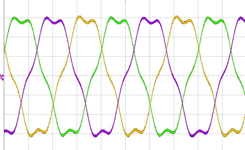
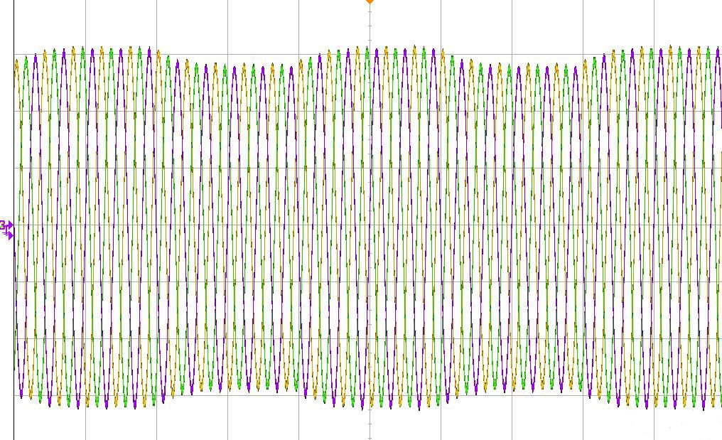
Simulation of power grid distortion Simulation of Voltage Fluctuations in the Power Grid
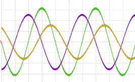
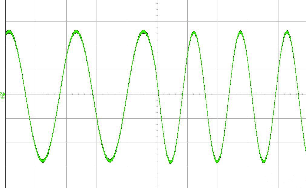
Simulation of Voltage Fluctuations in the Power Grid Transient simulation of power grid frequency
Solar cell array curved mold
The BD63/65 series DC power supply has a built-in SAS model, which can simulate and output the I-V curve/P-V curve of solar cells. Users can set a few simple parameters through the color touch screen on the front panel of the power supply to generate curves, which can be output to test the static and dynamic maximum power tracking (MPPT) performance of the photovoltaic inverter.
The BD63/65 series also has oscilloscope function, which can display the output curve and actual power point position in real time, as shown in the following figure:
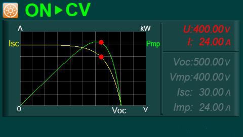
During the testing process, users do not need to calculate or refer to other instruments themselves, and can directly observe the screen to obtain tracking results.
Previous article:New Energy Vehicle OBC Power Supply Testing Solution
Next article:first page


